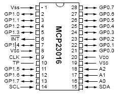
IO Expander, MCP23016
Datasheet MCP23016
Other stuff
Purchase from Digikey, $1.90
First of all don't buy this chip. Buy this one instead:
Datasheet, MCP23018
Other stuff
Purchase from Digikey, $1.81
It's faster, cheaper, and does not need the external RC circuit to determine the internal clock speed, saving a resistor, capacitor, and board space. There is also a SPI version known as the MCP23S18
• 16-bit remote bidirectional I/O port
• Fast I2C™ bus clock frequency (0 - 400 kbits/s)
• Three hardware address pins allow use of up to eight devices
• Open-drain interrupt output on input change
• Interrupt port capture register
• Input port polarity inversion
• High-current drive capability per I/O: ±25 mA
• Operating Supply Voltage: 2.0V to 5.5V
• 28-pin PDIP, 300 mil
The most unexpected aspect of this project was the relative slowness of the chip. These days it is so common to talk about Gigahertz and Megahertz, that we forget how freaking fast some of this stuff really is. But this chip surprised me by how slow it is. With the default I2c bus, I was only able to toggle all the pins (On, then Off) at a rate of 595Hz.
This loop below operates at about 595Hz (1.68ms).
void loop2(void) {
  write_io(GP0,255);   // all on  port 0
  write_io(GP1,255);   // all on  port 1
  write_io(GP0,0);     // all off port 0
  write_io(GP1,0);     // all off port 1
}
If I add trick code below, to the setup subroutine, to change the I2c rate, I can get up to about 980Hz (1.02ms).
It changes the I2c bus from the default rate of 100K to 275K. If I go any more, I start to get failures within a few seconds. I think the 275K is even a little too edgy, and unreliable for anything but speed tests.
  #define CPU_FREQ 16000000L
  #define TWI_FREQ 275000L
  TWBR = ((CPU_FREQ / TWI_FREQ) - 16) / 2;
I also tried to inline the function call. It was slightly faster but not significant, and certainly not worth the wordy code. For some reason I thought that the compiler would do that sort of thing by it's self. It's probably something they only do for PC that have crap load of memory to spare.
The loop below achieved a rate of 128kHz, using a standard 16MHz ATMEGA168 processor. That is like 128 times faster.
void loop(void) {
  digitalWrite(13, HIGH);
  digitalWrite(13, LOW);
}
The datasheet describes the external RC circuit used to set the internal clock speed (about 1MHz). They specify a 3.9K resistor and a 33pf cap. The closest I had was a 36pf cap. I works for everything I played with but maybe the correct cap would speed things up a bit.
My test code:
// MCP23016 I/O Expander
// Can toggle both ports (16 pins) at rates up to 595Hz (1.68ms)
// Arduino analog input 5 - I2C SCL
// Arduino analog input 4 - I2C SDA

#include

//Address of MCP23016 IO Expander, 8 addresses available
#define io_address        B00100000

// MCP23016 command byte to register relationship
#define GP0        0x00  // Data Port, Current status of pins
#define GP1        0x01  // Data Port, Current status of pins
#define OLAT0      0x02  // Output Latch, Current status of latched pins
#define OLAT1      0x03  // Output Latch, Current status of latched pins
#define IPOL0      0x04  // Input polarity, 0-normal, 1-inverted
#define IPOL1      0x05  // Input polarity, 0-normal, 1-inverted
#define IODIR0     0x06  // IO Direction, 0-output, 1-input
#define IODIR1     0x07  // IO Direction, 0-output, 1-input
#define INTCAP0    0x08  // Interrupt capture, Read-Only, value of port that generated the interrupt
#define INTCAP1    0x09  // Interrupt capture, Read-Only, value of port that generated the interrupt
#define IOCON0     0x0A  // IO Expander Control, Sampling frequency ofGP pins, 0-normal, 1-fast
#define IOCON1     0x0B  // IO Expander Control, Sampling frequency ofGP pins, 0-normal, 1-fast

//IO Bank 0
#define IO_gp00           B00000001
#define IO_gp01           B00000010
#define IO_gp02           B00000100
#define IO_gp03           B00001000
#define IO_gp04           B00010000
#define IO_pg05           B00100000
#define IO_gp06           B01000000
#define IO_gp07           B10000000

//IO Bank 1
#define IO_gp10           B00000001
#define IO_gp11           B00000010
#define IO_gp12           B00000100
#define IO_gp13           B00001000
#define IO_gp14           B00010000
#define IO_pg15           B00100000
#define IO_gp16           B01000000
#define IO_gp17           B10000000


///////////////////////////////////////////////////////////////////////////////////////////////////////
void setup(void) {
  //Serial.begin(115200);  // start serial for output

  Wire.begin();          // join i2c bus (address optional for master)

  // Special speedup of I2c bus from 100K to 275K
  // Going from about 595Hz (1.68ms) to 980Hz (1.02ms)
  #define CPU_FREQ 16000000L
  #define TWI_FREQ 200000L
  TWBR = ((CPU_FREQ / TWI_FREQ) - 16) / 2;

  write_io(IODIR0,0);
  write_io(IODIR1,0);
  write_io(GP0,0);
  write_io(GP1,0);

  pinMode(13, OUTPUT);

}

///////////////////////////////////////////////////////////////////////////////////////////////////////
void loop(void) {
  write_io(GP0,0);    // all off
  write_io(GP1,0);    // all off

  write_io(GP0,255);  // all on
  write_io(GP1,255);  // all on except the buzzer
}

///////////////////////////////////////////////////////////////////////////////////////////////////////
int read_io(int cmd_reg) {
  Wire.beginTransmission(io_address);
  Wire.send(cmd_reg);
  Wire.endTransmission();
  Wire.requestFrom(io_address, 1);
  return Wire.receive();
}

///////////////////////////////////////////////////////////////////////////////////////////////////////
void write_io(int cmd_reg, int push_this) {
  Wire.beginTransmission(io_address);
  Wire.send(cmd_reg);
  Wire.send(push_this);
  Wire.endTransmission();
}

///////////////////////////////////////////////////////////////////////////////////////////////////////
created: Dec. 1, 2013, 1:01 a.m.
modified: April 14, 2019, 12:50 a.m.