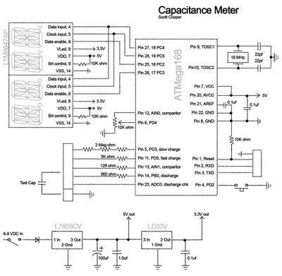
Capacitance Meter
Arduino Capacitance Meter and RC time constants
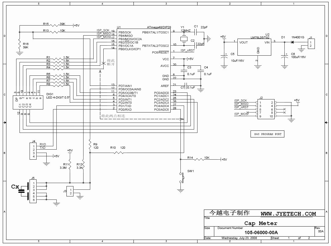
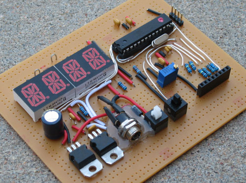
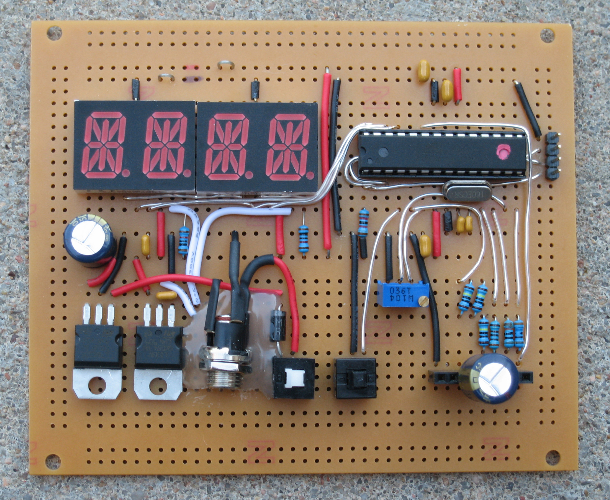
Sparkfun kit
Sparkfun kit, schematic
http://elm-chan.org/works/cmc/report.html
More capacitance info
I really need to get some thinner wire for these kinds of things. Dragging around a solid 20 gauge wire around my breadboard to carry fractions of an amp is silly.
/* RCTiming_capacitance_meter
*  Paul Badger 2008
*  Demonstrates use of RC time constants to measure the value of a capacitor
*
* Theory   A capcitor will charge, through a resistor, in one time constant, defined as T seconds where
*    TC = R * C
*
*    TC = time constant period in seconds
*    R = resistance in ohms
*    C = capacitance in farads (1 microfarad (ufd) = .0000001 farad = 10^-6 farads )
*
*    The capacitor's voltage at one time constant is defined as 63.2% of the charging voltage.
*
*  Hardware setup:
*  Test Capacitor between common point and ground (positive side of an electrolytic capacitor to common)
*  Test Resistor between charge_pin and common point
*  220 ohm resistor between discharge_pin and common point
*  Wire between common point and analog_pin (A/D input)
*/

#define analog_pin            0   // analog pin for measuring capacitor voltage
#define discharge_pin         8   // pin to discharge the capacitor
#define analog_voltage_pin    0   // pin 14 to read the discharge value
#define comparitor_state_pin  4   // pin
int fast_charge_pin         = 5;  // pin to charge the capacitor - connected to one end of the charging resistor
int slow_charge_pin         = 3;  // pin to charge the capacitor - connected to one end of the charging resistor
int current_charge_pin      = 0;
int calibrate_pin           = 2;
float resistorValue;              // change this to whatever resistor value you are using
                                  // F formatter tells compliler it's a floating point value
volatile byte  event;
#define  total_chars        4
#define  clock_pin          19       // set clock pin
int   data_enable_pins[] = {17, 16}; // set slave select pins
int   data_pins[]        = {18, 18}; // set master out, slave in pins
int   font[64];
int   c;
char  buf[16]           = "";
unsigned long calibrate_time = 184; // Initial calibration value unsigned long start_time;
unsigned long elapsed_time;
volatile unsigned int count = 0;
volatile unsigned long interrupt_time;
float micro_farads;                // floating point variable to preserve precision, make calculations
float nano_farads;
float pico_farads;

///////////////////////////////////////////////////////////////////////////////////////////////////////
void setup(){
	pinMode(analog_voltage_pin, INPUT);
	Serial.begin(19200);            // initialize serial transmission for debugging
	setup_led();

	// Set comparitor AIN1 (positive pin) to 3.160v, 63.212% * 5v, time constant 1
	// Time constant  1:  63.212%
	// Time constant  2:  86.466%
	// Time constant 10:  99.995%
	// More info at:  http://www.allaboutcircuits.com/vol_1/chpt_16/4.html

	pinMode(comparitor_state_pin, OUTPUT);
	digitalWrite(comparitor_state_pin, HIGH);
	pinMode(calibrate_pin, INPUT);
	digitalWrite(calibrate_pin, HIGH); //Turn on pull up resistors
	ACSR =   (0< 1) {}
	delay(100);
}

///////////////////////////////////////////////////////////////////////////////////////////////////////
char *ftoa(char *a, double f, int precision) {
	long p[] = {0,10,100,1000,10000,100000,1000000,10000000,100000000};
	char *ret = a;
	long heiltal = (long)f;
	itoa(heiltal, a, 10);
	while (*a != '\\0') a++;
	*a++ = '.';
	long desimal = abs((long)((f - heiltal) * p[precision]));
	itoa(desimal, a, 10);
	return ret;
}

///////////////////////////////////////////////////////////////////////////////////////////////////////
void output_results(){
	unsigned long time;
	char stmp[20];
	//char ascii[16];
	Serial.print("Elapsed: ");
	Serial.print(elapsed_time);
	Serial.print("     Calibrate: ");
	Serial.print(calibrate_time);
	Serial.print("     Resistance: ");
	Serial.print(resistorValue);
	if(elapsed_time > calibrate_time) {
		time = elapsed_time - calibrate_time;
	} else {
		time = 0;
	}
	Serial.print("     Time: ");
	Serial.print(time);
	// convert microseconds to seconds ( 10^-6 ) and Farads to micro_farads ( 10^6 ),  net 1
	micro_farads = ((float)time / resistorValue);
	if (micro_farads >= 1){
		//Serial.print((long)micro_farads);
		//Serial.println(" micro_farads");
		Serial.print("    ");
		Serial.print(micro_farads);
		Serial.print(" micro_farads");
		format_for_led (micro_farads, 'u');
	} else if (micro_farads >= 0.001){
		// if value is smaller than one microFarad, convert to nano_farads (10^-9 Farad).
		// This is  a workaround because Serial.print will not print floats
		nano_farads = micro_farads * 1000.0;		// multiply by 1000 to convert to nano_farads (10^-9 Farads)
		Serial.print("    ");
		Serial.print(nano_farads);
		Serial.print(" nano_farads");
		format_for_led (nano_farads, 'n');
	} else {
		// if value is smaller than one microFarad, convert to nano_farads (10^-9 Farad).
		// This is  a workaround because Serial.print will not print floats
		pico_farads = micro_farads * 1000000.0;		// multiply by 1000000 to convert to pico_farads
		Serial.print("    ");
		Serial.print(pico_farads);
		Serial.print(" pico_farads");
		format_for_led (pico_farads, 'p');
	}
	Serial.println();
}

///////////////////////////////////////////////////////////////////////////////////////////////////////
void format_for_led (float farads, char scale) {   char ascii[8];
	float temp = farads;
	//temp = 314.159265;
	if (temp >= 999.0) {
		sprintf(ascii, "OVER ", 1);
	} else {
		int temp1 = (temp - (int)temp) * 100;
		//Serial.print("    temp: ");
		//Serial.print(temp);
		//Serial.print("    temp1: ");
		//Serial.print(temp1);
		sprintf(ascii, "%0d.%02d", (int)temp, abs(temp1));
		//Serial.print("    ascii-1: ");
		//Serial.print(ascii);
		sprintf(ascii, "%-4.4s%c ", ascii, scale);
		//Serial.print("    ascii-2: ");
		//Serial.print(ascii);
	}
	print_led(ascii);
	Serial.print("    Display: ");
	Serial.print(ascii);
	Serial.print("    ");
}

///////////////////////////////////////////////////////////////////////////////////////////////////////
// LITE-ON, LTP-8647AP, 2 digit, 14-Segment Red LED
// Jameco.com, part no. 1955933, $2.95
// http://www.jameco.com/webapp/wcs/stores/servlet/Product_10001_10001_1955933_-1
//
// Code by Scott Cooper
// The code is setup to multiplex the data_pins and the data_enable_pins.
// This allows for a single ATMEGA168 to run up to 100 chips or 200 characters at a time (10x10)
// In this example the first chips is connected to pins 3 and 5.
// The second chip is connected to pins 4 and 6.
// All chips will use the same clock.
// The only pins needed to run the LTP-8647 chip:
//       4  data enable
//       5  clock
//       6  data
//       7  +5vdc
//       8  +3.3vdc
//       9  12k resistor going to Gnd, brightness
//      14  Gnd
///////////////////////////////////////////////////////////////////////////////////////////////////////
void setup_led() {
	// Add 32 to the font index to get the corresponding ASCII value

	font[0]  = 0;     // space
	font[1]  = 6144;  // !
	font[2]  = 272;   // "
	font[3]  = 16383; // #
	font[4]  = 11730; // $
	font[5]  = 2541;  // %
	font[6]  = 11309; // &
	font[7]  = 8;     // '
	font[8]  = 12;    // (
	font[9]  = 33;    // )
	font[10] = 255;   // *
	font[11] = 210;   // +
	font[12] = 1;     // ,
	font[13] = 192;   // -
	font[14] = 1666;  // .
	font[15] = 9;     // /
	font[16] = 16137; // 0
	font[17] = 6144;  // 1
	font[18] = 14016; // 2
	font[19] = 15424; // 3
	font[20] = 6592;  // 4
	font[21] = 9604;  // 5
	font[22] = 12224; // 6
	font[23] = 14336; // 7
	font[24] = 16320; // 8
	font[25] = 15808; // 9
	font[26] = 18;    // :
	font[27] = 17;    // ;
	font[28] = 12;    // <
	font[29] = 1216;  // =
	font[30] = 33;    // >
	font[31] = 12354; //
	font[32] = 14160; // @
	font[33] = 15296; // A
	font[34] = 15442; // B
	font[35] = 9984;  // C
	font[36] = 15378; // D
	font[37] = 10176; // E
	font[38] = 9088;  // F
	font[39] = 12096; // G
	font[40] = 7104;  // H
	font[41] = 18;    // I
	font[42] = 7680;  // J
	font[43] = 908;   // K
	font[44] = 1792;  // L
	font[45] = 6952;  // M
	font[46] = 6948;  // N
	font[47] = 16128; // O
	font[48] = 13248; // P
	font[49] = 16132; // Q
	font[50] = 13252; // R
	font[51] = 11712; // S
	font[52] = 8210;  // T
	font[53] = 7936;  // U
	font[54] = 777;   // V
	font[55] = 6917;  // W
	font[56] = 45;    // X
	font[57] = 42;    // Y
	font[58] = 9225;  // Z
	font[59] = 9984;  // [
	font[60] = 36;    // backslash
	font[61] = 15360; // ]
	font[62] = 12297; // ^
	font[63] = 1024;  // _

  pinMode(clock_pin, OUTPUT);                // set SCK pin to output

  for (int i=0; i     pinMode(data_enable_pins[i], OUTPUT);    // set CS pin to output
    digitalWrite(data_enable_pins[i], HIGH); // hold slave select 1 pin high, so that chip is not selected to begin with
  }

  for (int i=0; i     pinMode(data_pins[i], OUTPUT);           // set MOSI pin to output
  }

  print_led("    ");
}

///////////////////////////////////////////////////////////////////////////////////////////////////////
void print_led (char mystr[]) {
  for (int i=0; i     spi_out(data_pins[(i+1)/2], data_enable_pins[(i+1)/2], mystr[i],  mystr[i+1]);
  }
}

///////////////////////////////////////////////////////////////////////////////////////////////////////
void spi_out(int data_pin, int data_enable_pin, char c1, char c2) {
  unsigned long working;

  if (c1 >= 97 && c1 <= 122) { c1-=32; }  // check for lower case
  if (c2 >= 97 && c2 <= 122) { c2-=32; }  // check for lower case
  if (c1 < 32) { c1=' '; }                // check for too small
  if (c2 < 32) { c2=' '; }                // check for too small
  if (c1 > 95) { c1=' '; }                // check for too big
  if (c2 > 95) { c2=' '; }                // check for too big

  c1-=32;
  c2-=32;

  working = 1;
  working = working << 14;
  working += font[c2];
  working = working << 14;
  working += font[c1];
  working = working << 3;
  // Bits 32, 33 & 34 are not accessible because the long is only 32 bits.

  digitalWrite(data_enable_pin, LOW); // set low to enable this led.

  for(int i = 0; i <= 35; i++) {
    digitalWrite(clock_pin, LOW);

    //if(i == 2) { Serial.print(" "); }
    //if(i == 16) { Serial.print(" "); }
    //if(i == 30) { Serial.print(" "); }
    //if(i == 33) { Serial.print(" "); }

    if (working > 2147483647) { // test the most significant bit
      //Serial.print("1");
      digitalWrite (data_pin, HIGH); // if it is a 1 (ie. B1XXXXXXX), set the master out pin high
    } else {
      //Serial.print("0");
      digitalWrite (data_pin, LOW); // if it is not 1 (ie. B0XXXXXXX), set the master out pin low
    }
    digitalWrite (clock_pin,HIGH); // set clock high, the pot IC will read the bit into its register
    working = working << 1;
  }

  //Serial.print("  ");
  //Serial.print(c2, BYTE);
  //Serial.print("  ");
  //Serial.print(c1, BYTE);
  //Serial.println();
  digitalWrite(data_enable_pin, HIGH); // set high to disable this led.
}
created: Dec. 1, 2013, 1:01 a.m.
modified: April 14, 2019, 12:44 a.m.